MAXX 1200HD/2470HD CPU FAN REPLACEMENT
Caution – Use standard electrical safety and ESD procedures at all times.
*Note that when replacing a CPU fan in the field, to avoid having to remove the motherboard from the chassis, the fan legs must be trimmed to avoid bottoming out on the chassis, which prevents proper installation. CPU fan replacements purchased from 360 Systems will already be properly trimmed. Replacement fans sourced elsewhere will need to be modified as shown. Trim legs in the locked position, then unlock to install. To lock, push the white and black parts together until they lock. To unlock, rotate the black part in the direction of the arrow, then pull up on it until it pops out, then rotate it back to the initial position so it will lock again during installation.
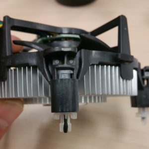
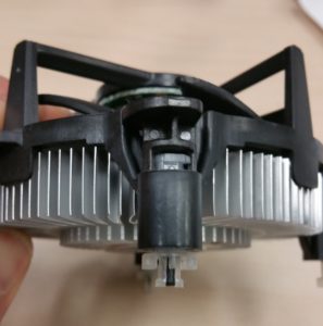
Before Trimming After Trimming
CPU Fan Replacement Procedure:
- Remove top cover.
- Unplug power cable and ribbon cables from audio board.
- Remove audio board. Note: there is a ribbon cable on the underside of the audio board connecting the audio board to the GPIO board.
- Turn CPU fan legs ¼ turn in direction indicated by arrow using a flat blade screwdriver.
- Pull up on CPU fan legs to release them from the motherboard.
- Remove old fan from unit.
- Clean old thermal compound from CPU surface.
- Place new CPU fan into unit, aligning white plastic legs with holes in motherboard.
- Press down VERY FIRMLY on each of the CPU fan legs, one at a time, until it locks into place with an audible click. This requires quite a bit of force, and is normal. Start with one of the legs nearer the center of the motherboard, then the one diagonal from it.
- Route CPU fan cable away from fan blades and around the heatsink.
- Plug CPU fan into CPU fan header of motherboard.
- Install audio board back into unit, taking care to plug ribbon cable back into GPIO board on the underside of audio board.
- Reconnect power cable and ribbon cables to audio board.
- Replace top cover.